Telecaster Wiring Diagram: 3-Way, 4-Way & 5-Way (2026)
Complete Telecaster wiring diagrams for 3-way, 4-way series/parallel, and 5-way super switch. Includes switch lug maps, parts lists, soldering tips, treble bleed mod, and step-by-step instructions with diagrams.
Telecaster Wiring Diagram: The Complete Guide
Wiring a Telecaster is a rite of passage for Fender enthusiasts. Whether you are chasing the vintage correct specs of a 1952 Blackguard or modernizing your axe with a 4-way series switch, understanding the circuit is the first step to tonal nirvana. This comprehensive guide covers the three most popular Telecaster wiring configurations: the standard 3-Way, the high-output 4-Way Mod, and the versatile 5-Way Super Switch.
Note: This guide features high-resolution diagrams, switch lug maps, and detailed component explanations to help you solder with confidence.
What You’ll Learn
By the end of this guide, you will understand:
- The Signal Path: How your guitar signal travels from pickup to jack.
- Component Physics: Why 250k pots are standard and how capacitor materials change your tone.
- Advanced Mods: How to add clarity with a Treble Bleed and power with Series Wiring.
- Troubleshooting: How to fix ground loops and phase cancellation.
Parts and Tools Checklist
To get professional results, you need professional components. Cheap electronics are the #1 cause of tone loss in imported guitars.
Core Components:
- Pickups: 2x Single-Coil Telecaster Pickups (Bridge & Neck).
- Switch: 1x Blade Switch (Oak Grigsby or CRL recommended).
- Pots: 2x 250k Audio Taper Potentiometers (Solid shaft for set-screw knobs, Split shaft for push-on).
- Capacitor: 1x 0.047 µF (Vintage Darker) or 0.022 µF (Modern Brighter).
- Wire: Gavitt Vintage Pushback Cloth Wire (22 AWG).
- Jack: Switchcraft 1/4" Mono Output Jack.
Recommended products:
- Parts
- Tools
Standard Telecaster Wiring (3‑Way)
This is the configuration that started it all. Used on the vast majority of Telecasters from the 1950s to today, the 3-way switch offers a simple, intuitive layout.
The Logic of the Circuit
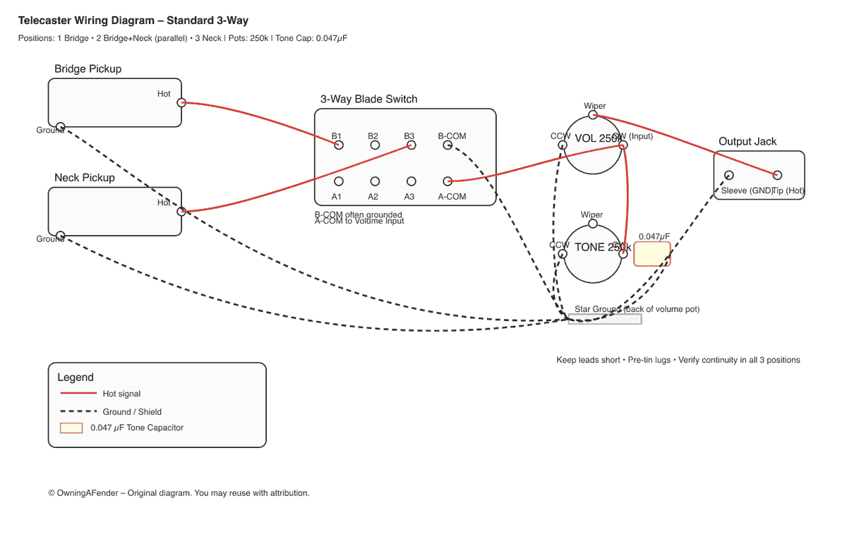
The 3-way switch connects specific pickups to the volume pot input.
- Position 1 (Back): The switch engages the Bridge Pickup only. This is the "Twang" setting—bright, cutting, and perfect for country leads or distorted rock riffs.
- Position 2 (Middle): The switch connects Both Pickups in Parallel. "Parallel" means the current has two paths to flow through. This halves the impedance, resulting in a cleaner, scooped tone with "quack" and slightly less volume than the series counterpart. It is also hum-canceling if your pickups are RWRP (Reverse Wound, Reverse Polarity).
- Position 3 (Front): The switch engages the Neck Pickup only. This is the warm, bluesy, "jazzy" tone that many people underestimate on a Telecaster.
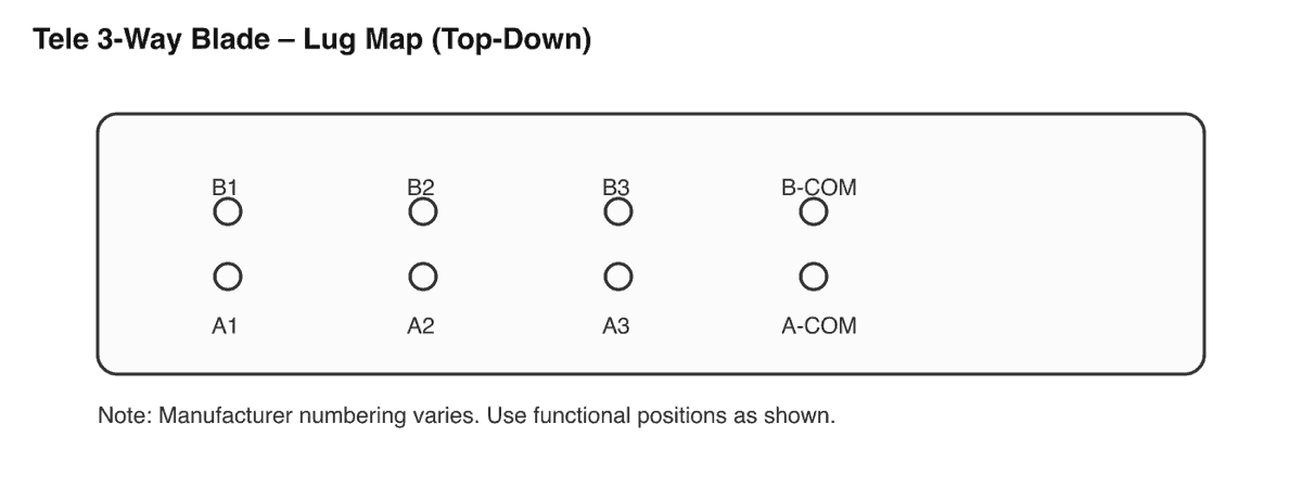
3‑Way Switch Lug Map
Understanding the switch terminals (lugs) is key. The standard 3-way switch has 8 lugs (4 per side).
The Diagram
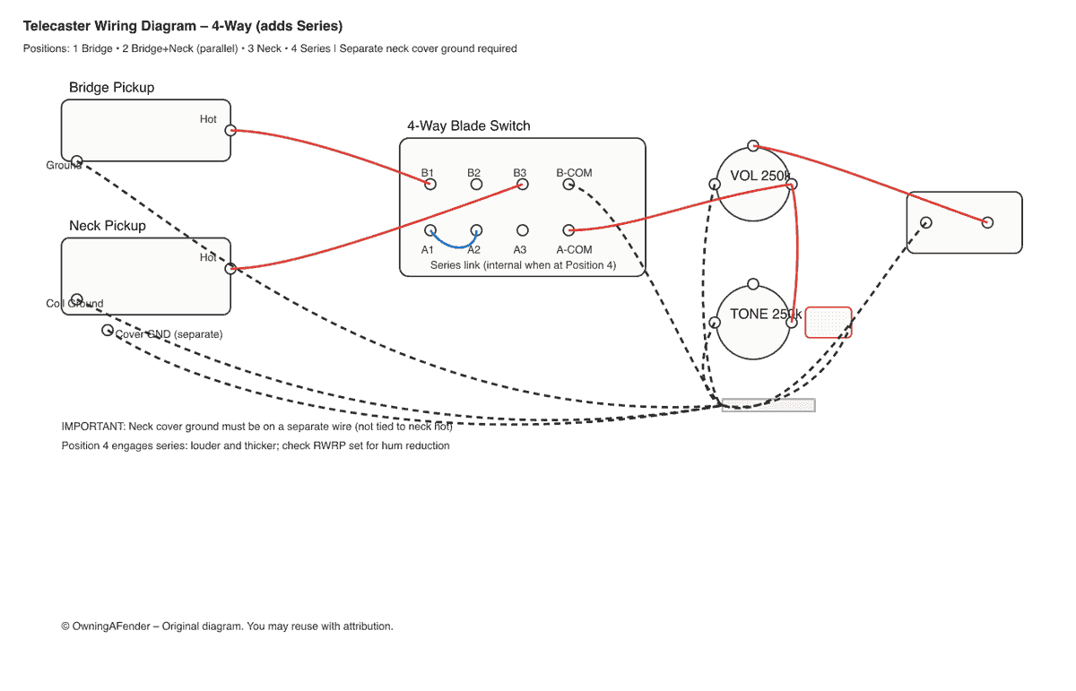
4‑Way Tele Wiring Diagram (The "Series" Mod)
If you only do one mod to your Telecaster, make it this one. The 4-Way Mod adds a fourth position that runs both pickups in Series rather than parallel.
Series vs. Parallel: The Physics
- Parallel (Standard): Think of two garden hoses running side-by-side. You get flow from both, but the pressure (output) is shared. The tone is bright and polite.
- Series (Mod): Think of connecting one garden hose to the end of the other. The pressure (output) builds up. In guitar terms, the output of the Neck pickup feeds into the Bridge pickup. This sums their resistance (e.g., 7k + 7k = 14k), creating a loud, thick, humbucker-like tone.
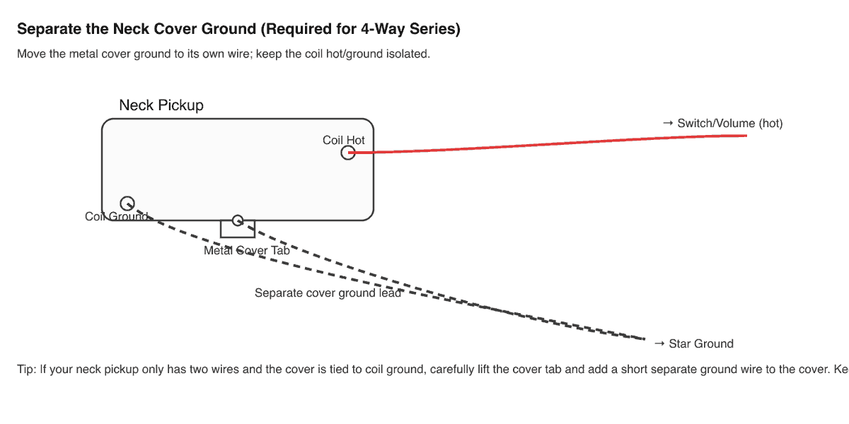
Critical Step: Ground Separation
To make this work, you must modify your neck pickup. Standard Tele neck pickups connect the metal cover's ground to the signal negative (black wire). In a series circuit, the "negative" of the neck pickup becomes the "positive" input for the bridge pickup. If you don't separate the ground, the metal cover will become live, causing massive buzz when touched. Solution: Cut the jumper connecting the cover to the eyelet ground, and solder a dedicated 3rd wire to the cover tab. Connect this new wire to the back of the volume pot.
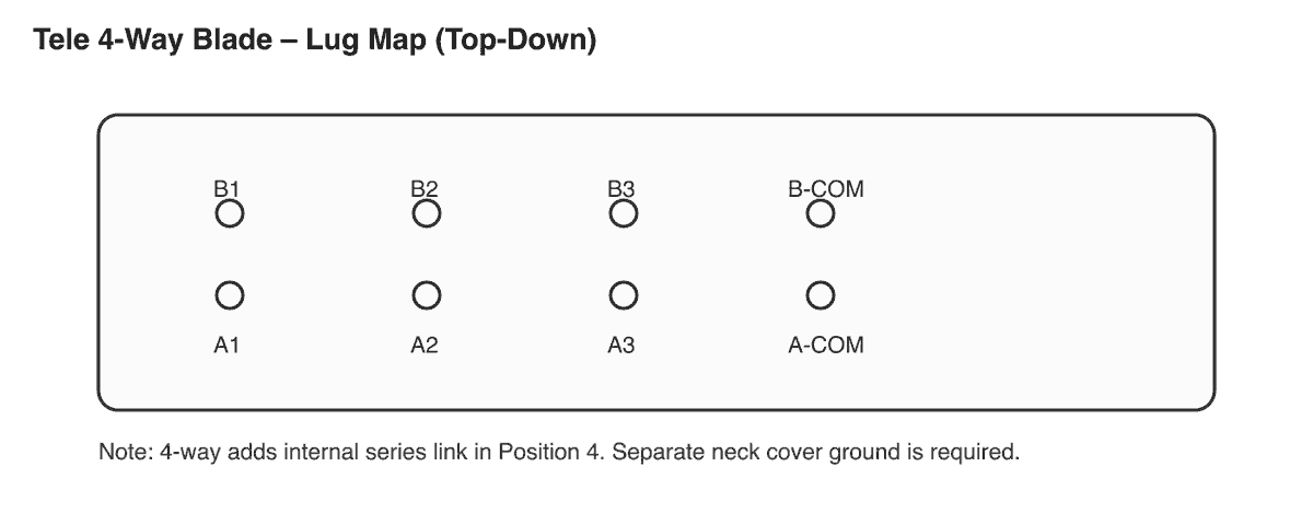
The 4-Way Diagram
Deep Dive: The Treble Bleed Mod
One common complaint with Telecasters is that they get "muddy" when you roll down the volume knob. This happens because the volume pot acts as a low-pass filter as resistance increases, dumping high frequencies to ground.
The Fix: Treble Bleed Circuit
A Treble Bleed is a tiny capacitor (and usually a resistor) soldered across the input and output lugs of your volume pot. It allows high frequencies to "bleed" through to the output even when the volume is turned down, keeping your tone crisp at volume 5.
Recommended Values for Telecaster:
- Duncan Style: 0.002µF capacitor in parallel with a 100k resistor. (Best for smooth taper).
- Kinman Style: 0.0012µF capacitor in series with a 130k resistor.
Component "Secret Sauce": Pots and Caps
Why do specific components matter? It's not just snake oil; it's physics.
Potentiometers: 250k vs 500k
The resistance of your volume pot determines how much high-end escapes to ground even when fully open.
- 250k Pots: The standard for Telecasters. They bleed off just enough harsh treble to tame the ceramic/alnico single coils.
- 500k Pots: Standard for Humbuckers. If you put these in a Tele, it will sound "ice-picky" and painfully bright.
Capacitors: Materials Matter
The tone capacitor only affects your sound when you roll down the Tone knob.
- Ceramic Disc: The standard production cap. Can sound a bit "gritty" or harsh when rolled off.
- Orange Drop (Polyester): The upgrade standard. Smooth, consistent roll-off.
- Paper-in-Oil (PIO): The vintage choice. Expensive, but treasured for a very musical, vocal-like quality when using the tone control.
Understanding the Signal Path: How Your Tele Works Electrically
Before you wire anything, understanding what happens electrically helps you troubleshoot problems and design custom circuits.
The Complete Signal Chain
| Component | Function | Signal Travel Direction |
|---|---|---|
| Pickup | Converts string vibration to electrical signal | START → |
| Switch | Routes signal from selected pickup(s) | → |
| Volume Pot (Input) | Receives signal from switch | → |
| Volume Pot (Output) | Attenuates signal (when turned down) | → |
| Tone Pot (Wiper) | Bleeds high frequencies to ground via capacitor | (Side path) |
| Output Jack (Tip) | Sends signal to amplifier | → END |
| Ground System | Returns signal to pickup (completing circuit) | ← (Return) |
What "Parallel" Actually Means
When you run pickups in parallel (standard middle position):
- Both pickups connect their hot wires to the switch output.
- Both pickups connect their grounds together.
- The signal divides between two paths before rejoining.
Result: Total impedance is lower than either pickup alone (typically ~3.5k for two 7k pickups). This creates a brighter, thinner sound with slightly less output than either pickup solo—but often with pleasant "quack" and phase interaction.
What "Series" Actually Means
When you run pickups in series (4-way mod):
- The hot of the neck pickup connects to the switch output.
- The ground of the neck pickup connects to the hot of the bridge pickup.
- The ground of the bridge pickup goes to circuit ground.
Result: Impedances add (7k + 7k = 14k). Output increases significantly. The tone becomes fuller, warmer, and humbucker-like—without the sound of an actual humbucker. This is what makes the 4-way mod so popular.
Grounding Fundamentals: Avoiding Hum and Buzz
Grounding issues cause 90% of wiring problems. Understanding ground theory prevents hours of troubleshooting.
The "Star Grounding" Method
Instead of chaining grounds from component to component, professional wiring uses star grounding:
- Choose a single grounding point. On Telecasters, this is typically the back casing of the volume pot.
- Run all ground wires to that single point. This includes:
- Pickup ground wires
- Tone pot casing
- Output jack sleeve wire
- Bridge ground wire
- Any shielding connections
- Avoid ground loops. Never create circular paths where ground could travel multiple routes.
Why Star Grounding Matters
Ground loops act as antennas, picking up electromagnetic interference (EMI) from power lines, lights, and equipment. A proper star ground gives interference only one path—directly to the output jack—where it can be shunted to the amplifier's ground.
The Critical Bridge Ground
Telecasters are unique: the metal bridge plate touches the strings, and a ground wire under the bridge plate connects to the volume pot. This grounds your body (through the strings) when you touch them, eliminating the "60-cycle hum" that appears when hands leave the strings.
Common Problem: If this wire breaks or wasn't installed, your guitar will be silent when strings are touched and will buzz loudly when your hands leave the strings.
Soldering Best Practices
Good solder joints are the difference between a reliable instrument and a frustrating one.
Temperature Settings
| Component | Recommended Temperature | Notes |
|---|---|---|
| Pot lugs | 350-380°C (660-720°F) | Higher mass, needs more heat |
| Switch lugs | 320-350°C (610-660°F) | Medium mass |
| Wire splices | 300-320°C (570-610°F) | Lower mass, avoid overheating |
| Pickup leads | 280-300°C (540-570°F) | Delicate, brief contact only |
The Perfect Solder Joint
- Heat the component first, not the solder. Place the iron tip against the pot lug or switch terminal for 2-3 seconds.
- Apply solder to the opposite side. The hot component melts the solder, ensuring it flows into the joint.
- Hold still until cooled. Moving causes a "cold joint"—a dull, grainy connection that may work intermittently.
- Inspect the result. Good joints are shiny and slightly concave (like a Hershey's Kiss). Bad joints are dull, blobby, or cracked.
Avoiding Common Mistakes
- Don't overheat pots. Extended heat damages the carbon wiper inside. If the pot won't take solder after 5 seconds, stop—let it cool, then clean the lug with sandpaper.
- Pre-tin your wires. Twist stranded wire, apply solder before attaching to components. This speeds final assembly.
- Use flux-core solder. 60/40 rosin-core (not acid-core) is standard for electronics.
- Have a solder sucker ready. Mistakes happen. A desoldering pump or braid makes cleanup easy.
Advanced Wiring Modifications
Beyond the standard configurations, these mods expand your Telecaster's tonal range.
The "Eldred" Wiring (Blend Pot)
Instead of a standard tone control, install a blend pot that gradually mixes in the neck pickup while in bridge-only position. This gives infinite combinations between pure bridge and bridge+neck.
Components Needed: One 500k linear (B) taper pot replacing the tone pot.
Coil Tap (If Using Humbuckers)
If you've installed a humbucker in the neck or bridge, add a push-pull pot to split it to single-coil mode. This gives vintage Tele tone on demand while keeping humbucker power available.
Phase Reverse Switch
A mini-toggle wired between pickups creates an out-of-phase sound when both are active. The tone becomes thin, nasal, and "funky"—useful for rhythm work or Brian May-style leads.
Greasebucket Tone Circuit
Fender's "Greasebucket" mod uses a 0.022µF cap in series with a 4.7k resistor, plus a 0.1µF cap to ground. As you roll down tone, highs are cut without the "muddy" bass buildup of a standard tone circuit.
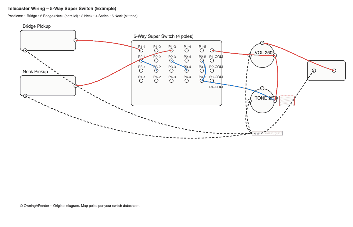
5‑Way Super Switch Wiring (Detailed)
For the adventurous, a 5-Way Super Switch allows you to have it all. Unlike a standard blade switch, a Super Switch has 4 separate poles, allowing for complex routing logic.
Popular 5-Way Layout:
- Bridge Only — Classic twang, unmodified
- Bridge + Neck (Parallel) — Quacky middle position, hum-canceling if RWRP
- Neck Only — Warm, jazzy rhythm tone
- Bridge + Neck (Series) — Thick, humbucker-like power
- Neck (Tone Bypass) — Captures the direct, uncolored sound of the pickup, bypassing the tone cap entirely
Advanced 5-Way Alternative:
- Bridge
- Bridge + Neck (Series)
- Bridge + Neck (Parallel)
- Neck
- Neck (Out of Phase with capacitor bleed)
Troubleshooting: Comprehensive Diagnosis Guide
Symptom-to-Cause Diagnostic Table
| Symptom | Likely Cause | Solution | Difficulty |
|---|---|---|---|
| Loud hum that stops when touching strings | Missing bridge ground | Ensure wire under bridge plate connects to star ground | Easy |
| Loud hum that continues when touching strings | Ground loop or failed shielding | Check for circular ground paths, verify star grounding | Medium |
| Thin, weak middle position | Pickups out of phase | Swap hot and ground on ONE pickup (usually bridge) | Easy |
| Scratchy noise when turning pots | Dirty pot internals | Spray DeoxIT F5 into pot casing, rotate 20x | Easy |
| No sound from one pickup | Cold solder joint or broken wire | Reflow all joints on that pickup's path, check continuity | Medium |
| No sound at all | Open circuit (broken wire, bad jack) | Use multimeter to trace signal path | Medium |
| Sound cuts out when cable is moved | Bad output jack connection | Resolder jack tip and sleeve terminals | Easy |
| Volume pot doesn't fully silence guitar | Wrong pot taper (linear vs audio) | Replace with 250k audio taper pot | Easy |
| Tone pot does nothing | Failed capacitor or disconnected wire | Check cap value, resolder connections | Easy |
| Buzzing from specific pickup only | Failing pickup or internal short | Test pickup resistance; should be 6-8k for standard Tele | Medium |
Using a Multimeter for Diagnosis
Essential Tests:
- Pickup Resistance: Set multimeter to 20k ohms. Touch probes to pickup hot and ground. A healthy Tele bridge reads 6-8k; neck reads 5-7k. Open circuit or near-zero indicates a failed pickup.
- Continuity Test: Set to continuity (beep) mode. Touch one probe to bridge metal, one to output jack sleeve. It should beep, confirming the ground path is intact.
- Cable Test: With guitar plugged in, flex the cable near both ends while testing continuity from plug tip to plug tip. Crackling or dropout indicates a bad cable.
Frequently Asked Questions (FAQ)
What is the standard Telecaster wiring diagram?
Answer: Standard Tele wiring uses a 3-way switch with three positions: Bridge only (Position 1, back), Bridge+Neck in parallel (Position 2, middle), and Neck only (Position 3, front). The circuit uses 250k audio taper potentiometers for both volume and tone, with a 0.047 µF tone capacitor connecting the tone pot wiper to ground. The switch common (output) feeds the volume pot input, and all grounds terminate at a star ground point on the back of the volume pot casing. This configuration has remained essentially unchanged since Leo Fender designed it in 1950.
Do I need a special pickup for the 4-way Telecaster wiring diagram?
Answer: No, but you must modify standard Tele neck pickups. Stock neck pickups connect the metal cover's ground to the signal negative (black wire). In a series circuit, the "negative" of the neck pickup becomes the "positive" input for the bridge pickup. If you don't separate the ground, the metal cover will become electrically "live," causing massive buzz when touched and potentially creating a safety hazard. The solution is to add a third wire: cut the internal jumper connecting the cover tab to the hot ground, then solder a dedicated wire from the cover tab directly to your star ground point.
Will the 4-way series position be humbucking?
Answer: Yes, it will be hum-reduced (though not perfectly silent) when both pickups are RWRP (Reverse Wound, Reverse Polarity) relative to each other, which is standard on most matched Telecaster pickup sets. The series position combines signals before any phase cancellation occurs, but the RWRP design causes external electromagnetic interference to cancel out. Output is significantly louder (nearly double) and the tone is thicker, warmer, and more humbucker-like than any other Tele position.
Can I use 500k pots with Telecaster single-coils?
Answer: You can, but proceed with caution. 500k pots allow more high-frequency content to reach the output (less treble bleeds to ground). With Telecaster single-coils—which are already bright by design—500k pots often sound "ice-picky," harsh, and fatiguing. Most players prefer 250k for traditional Tele tone. However, if you've installed darker-voiced pickups, wound to higher impedance, or added humbuckers, 500k pots may be appropriate. A compromise option is a 300k pot, which adds slight brightness without becoming harsh.
What capacitor value should I use?
Answer: The tone capacitor only affects sound when the tone knob is rolled down, acting as a low-pass filter. Common values:
- 0.047 µF (Vintage spec): Darker roll-off, more treble cut. Classic warm Telecaster rhythm tone.
- 0.022 µF (Modern spec): Brighter roll-off, more usable range on the tone knob. Many players prefer this for greater control.
- 0.033 µF: A compromise between vintage and modern.
The capacitor material (ceramic, polyester/Orange Drop, paper-in-oil) affects the character of the roll-off but not the amount. Ceramic is harsher; Orange Drop is smooth; PIO is vocal and musical—but differences are subtle.
Should I add a treble bleed circuit?
Answer: It depends on your playing style. If you frequently use your volume knob for dynamics (rolling down for clean parts, up for leads), a treble bleed prevents the muddy sound that occurs when the volume pot acts as a low-pass filter at lower settings. The most popular treble bleed values for Telecaster are:
- Duncan Style: 0.002µF capacitor in parallel with a 100k resistor. Smooth taper, retains high-end evenly.
- Kinman Style: 0.0012µF capacitor in series with a 130k resistor. More subtle effect.
If you always play with volume on 10, a treble bleed is unnecessary.
How do I know if my pickups are RWRP?
Answer: RWRP (Reverse Wound, Reverse Polarity) means one pickup is wound in the opposite direction with magnets reversed, causing hum-cancellation in the middle position. To test:
- Set your multimeter to DC millivolts.
- Touch a magnetized screwdriver to each pickup's pole pieces.
- Note which direction moves the needle (+ or -).
- If the neck and bridge read opposite polarities, they're RWRP.
Most modern matched Tele sets are RWRP; vintage-style sets (including many reissues) are not.
Why does my freshly wired Telecaster sound weak?
Answer: Several possibilities:
- Cold solder joints: Dull, grainy joints have high resistance. Reflow all connections.
- Wrong pot value: Using 500k or 1M pots with low-output single-coils can sound thin. Confirm 250k audio taper.
- Phase issue: If middle position is thin and weak, pickups are out of phase. Swap hot/ground on one pickup.
- High pickup distance: If pickups were lowered during work, raise them closer to strings (start at 4/64" bass, 3/64" treble, measured at last fret pressed).
- Worn strings: Old strings sound dull. Install fresh strings to evaluate your wiring work.
What is the Telecaster wiring diagram for the 3-way switch?
Answer: The Telecaster 3-way switch wiring is: Position 1 (back) = bridge pickup only; Position 2 (middle) = bridge and neck in parallel; Position 3 (front) = neck only. The switch common (output) goes to the volume pot input. Use 250k audio taper pots and a 0.047 µF (or 0.022 µF) tone cap. All grounds tie to a star ground on the back of the volume pot. See the 3-way switch lug map and diagram earlier in this guide for exact connections.
How do I wire a Telecaster?
Answer: Wire a Telecaster by (1) connecting the bridge and neck pickup hot wires to the 3-way switch input lugs, (2) running the switch common to the volume pot input, (3) wiring volume output to the tone pot input and tone wiper to ground via the capacitor, (4) running the volume output to the jack tip and tying all grounds (pickups, bridge, pots, jack sleeve) to one star ground. Use 250k pots, 22 AWG wire, and a Switchcraft jack. Follow the standard Telecaster wiring diagram in this guide for step-by-step lug-by-lug instructions.
For setup and playability after your wiring work, see our Ultimate Telecaster Setup Guide and Telecaster Truss Rod Adjustment.

Related Posts
Telecaster-Specific Guides
- Ultimate Telecaster Setup Guide - Complete setup process and specifications
- Telecaster Truss Rod Adjustment - Detailed neck relief adjustment techniques
- Best Strings for Telecaster - Complete string recommendations
- Telecaster String Gauge Selection Guide - Action height and string gauge selection
Other Fender Guitar Setup Guides
- Stratocaster Setup Guide - Complete Stratocaster setup process
- Jaguar Setup Guide - Offset guitar setup techniques
- Jazzmaster Setup Guide - Jazzmaster-specific setup procedures


